Total Performance, Chevy Style
The CERV II and the evolution of the Corvette, Part 1
When Ford broke with the AMA agreement and went racing, Chevrolet lost no time preparing its counterattack. In the vanguard was Zora Arkus-Duntov with a radical four-wheel driver known to the world as CERV II.
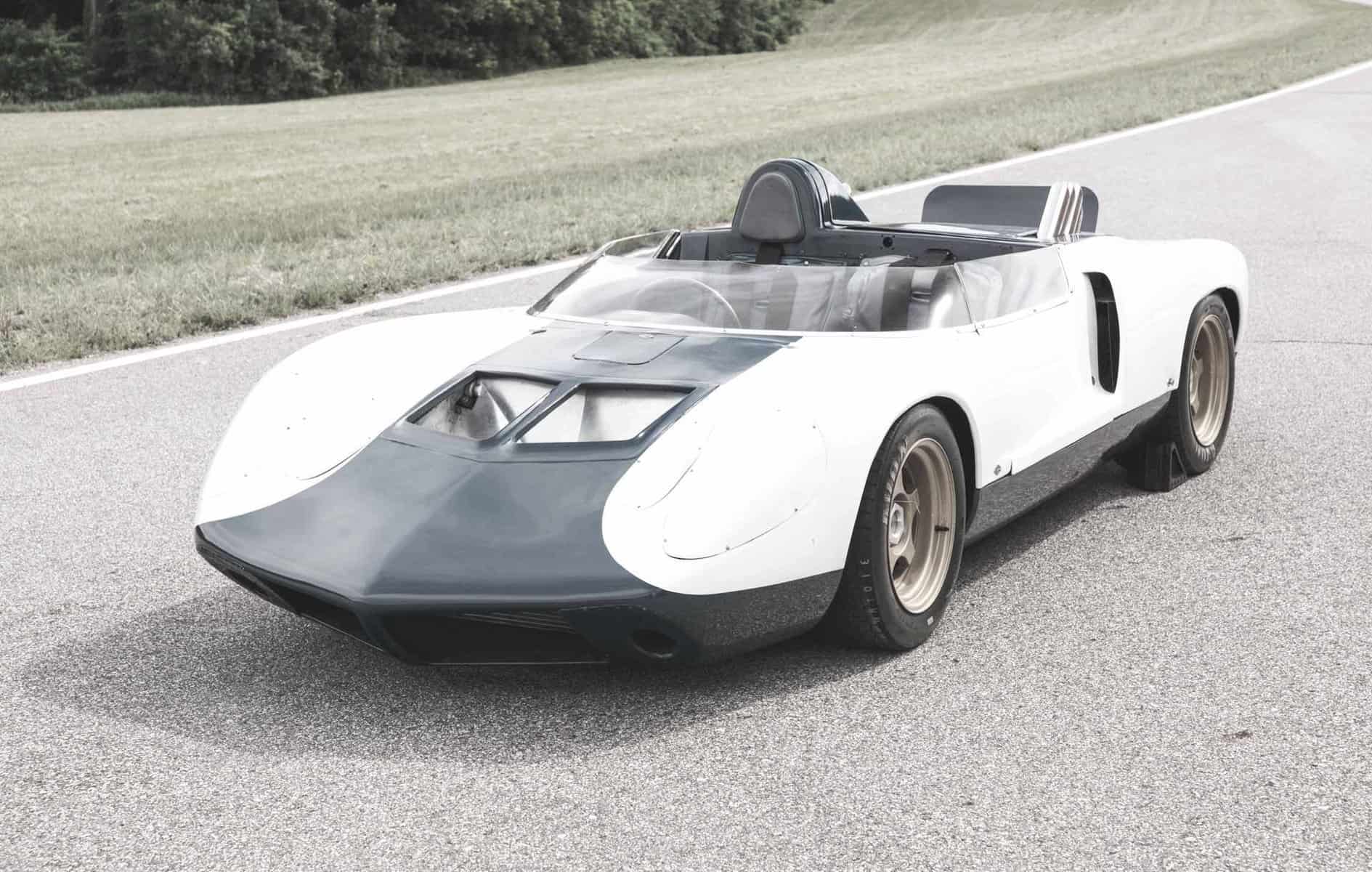
This amazing automobile was conceived in the autumn of 1963 as a contender for victory in the great international long-distance races. Styling staff marked the official start of project XP-817 as September 27, 1963. A year earlier Ford had unveiled its mid-engined Mustang at Watkins Glen. It was an early stage of Ford’s “Total Performance” initiative, openly promoted as the forerunner of a future Ford sports-racer to compete on the world’s great racetracks.
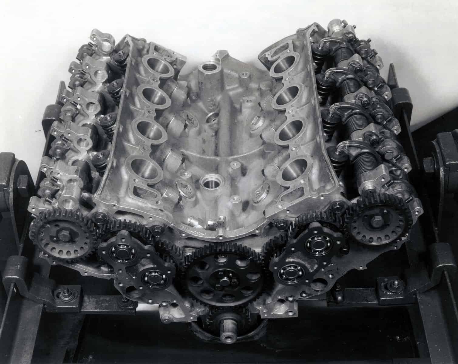
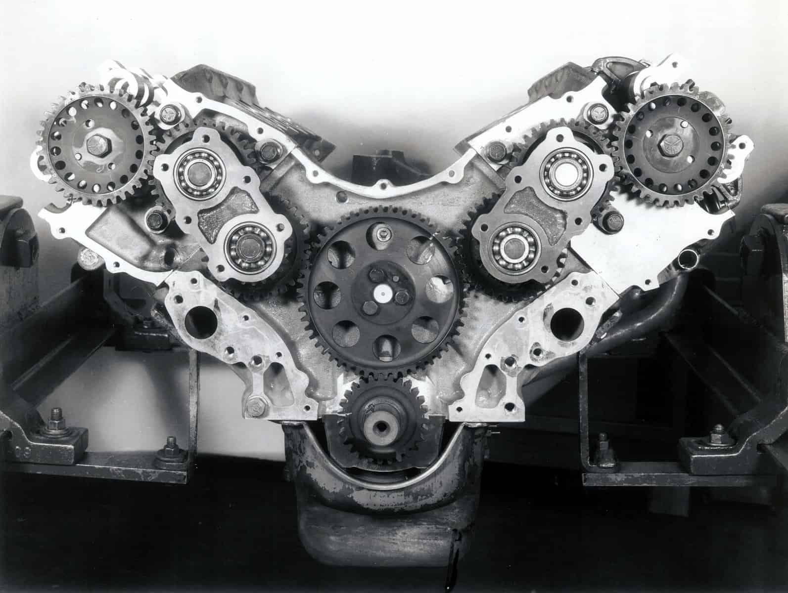
At that time the World Sports-Car Championship events posed no limit on engine size. This meant that Zora, his designer Walt Zetye, and his technicians Ernie Lumus and Bob Kethmann could think big when planning an engine for the car. Their choice was one of the most exotic V8s in Dr. Duntov’s capacious cabinet of power, a completely special aluminum engine. It had a single overhead cam on each bank, driven by a train of gears in pure racing-engine style. The cams operated two valves per cylinder through rocker arms, feeding hemispherical combustion chambers.
Displacing 377 cubic inches, 6.2 liters, this V8 was developed to produce more than 500 hp by Zora’s engine team of Cal Wade, Fred Frincke, and Denny Davis. While it was being tested in parallel, the engine actually used in the CERV II was an all-aluminum 377-cubic-inch engine with pushrod valve gear like the ones used in the Grand Sport Corvettes at the end of 1963. In fact the engines and other components in those GS racers were being evaluated in the December races at Nassau to determine their suitability for the CERV II.
The power unit installed in the CERV II prototype was fed fuel by Hilborn constant-flow injection instead of the Weber carburetors used in the Bahamas. This allowed methanol fuel to be used so that the output of the overhead-cam V8 could be simulated during development of the new car’s chassis.
Putting this power on the pavement was the next requirement. Thanks to Zora Duntov’s close relationship with Firestone, the CERV II was able to use the most advanced racing tires then available. Zora was the first engineer outside Firestone to be able to test the new wider low-profile tires it was developing late in 1963 for the 1964 Indy race. He found them highly adhesive and gratifyingly forgiving of driver error. Duntov chose the 9.50 x 15 size for all four wheels, on 8.5-inch rims cast of magnesium by Kelsey-Hayes. Knock-off hubs were fitted with the long-distance races in view.
All four wheels and tires were identical in size because Duntov had decided to equip the CERV II with four-wheel drive. The Belgian-born, Berlin-educated Duntov had been thinking about various ways of driving all four wheels since he saw the 4WD Bugatti Type 53 win a standing-start sprint event in 1935. The Bugatti was so strong on the straights but so poor in the corners that Zora thought there must be some way to combine good handling with the fine road grip given by four-wheel drive. In 1937 he presented some of his thoughts in a technical paper on four-wheel-driven racing cars.
In 1963 the first great wave of enthusiasm for 4WD racing cars was still half a dozen years in the future. Zora elected to use it because his calculations showed that it could provide a higher cornering speed as well as much-improved acceleration with a very powerful engine, more than offsetting the weight handicap of 125 pounds.
Early in the 1960s Chevrolet’s R&D department had been doing experimental work with torque-converter transmissions in racing cars that led directly to the Chevy-built unit used in the Chaparrals from 1964 onward. Zora had planned an automatic transmission for his 1962 CERV II study, but it was a pure mechanical power-shifted gearbox. Considering the torque-converter approach, less efficient but far simpler, Zora saw he could use it for his new car, which would be generously powered for its 1,900-pound design weight.
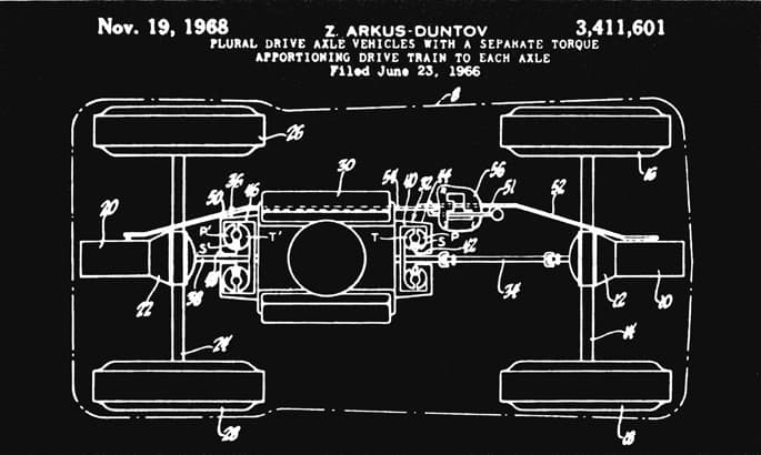
Zora took a big step further with his concept. He would drive the back wheels through one torque converter and the front wheels, from the front of the engine, through another one. It was a completely new principle on which Duntov lodged a U.S. patent on June 23, 1966.
Not pretending to be a torque-converter specialist, Zora Duntov presented the parameters of his proposed driveline to the experts of GM’s engineering staff. He gave them the information and his requirements. As planned, the CERV II (or GS-3, as it was then known, later GS-10) had a static front/rear weight distribution of 46.5/53.5. With a center of gravity 14 inches high, the proportion of weight on the front wheels would drop to only 32 percent when the car was accelerating at 1.0 g. — well within its capability. “What I want,” Zora told the experts, “are torque converters that will deliver 35 percent of the engine torque to the front wheels at low car speeds and up to 40 percent at higher speeds.”
Excepting schemes that use separate engines to drive the front and rear wheel pairs, this was the first time that anyone had tried to achieve a variation in the front/rear torque distribution of a four-wheel-drive car while it was in motion. Raymond P. Michnay of the engineering staff took on the job and handled it to perfection.

At the back of the engine, driving the rear wheels, Michnay specified an 11-inch Powerglide torque converter. He modified it so it didn’t approach a locked-up or nearly one-to-one drive condition until 4,500 rpm. Then for the front wheels he provided a 10-inch converter from a Corvair Powerglide, placed ahead of the front-wheel centerline just as it was ahead of the Corvair’s rear wheels. It was rotated in the same sense by the universal-jointed shaft running forward from the front end of the crankshaft. The front converter approached lockup at 4,100 rpm.
Performance calculations showed that with a low final drive ratio the CERV II would accelerate from zero to 60 mph in 2.8 seconds and reach a top speed of 115 mph. With a higher ratio maximum speed would go up to 183 mph and the time to reach 60 would be much longer — about four seconds. Deciding to have the best of both worlds, Duntov equipped both axles of CERV II with compact two-speed gearboxes like those used in the Chaparrals through 1965.
Controlled by a single cockpit lever, the gearboxes gave a direct drive and a 1.5:1 reduction. With a 3.55:1 axle ratio this gave speeds of 107 mph in low and 160 in high, at 6,500 rpm, taking into account the three-percent slippage in the converters above 6,000 rpm. The gearbox at the front had to be specially made with concentric shafts that allowed the torque converter to be overhung at the front of the chassis.
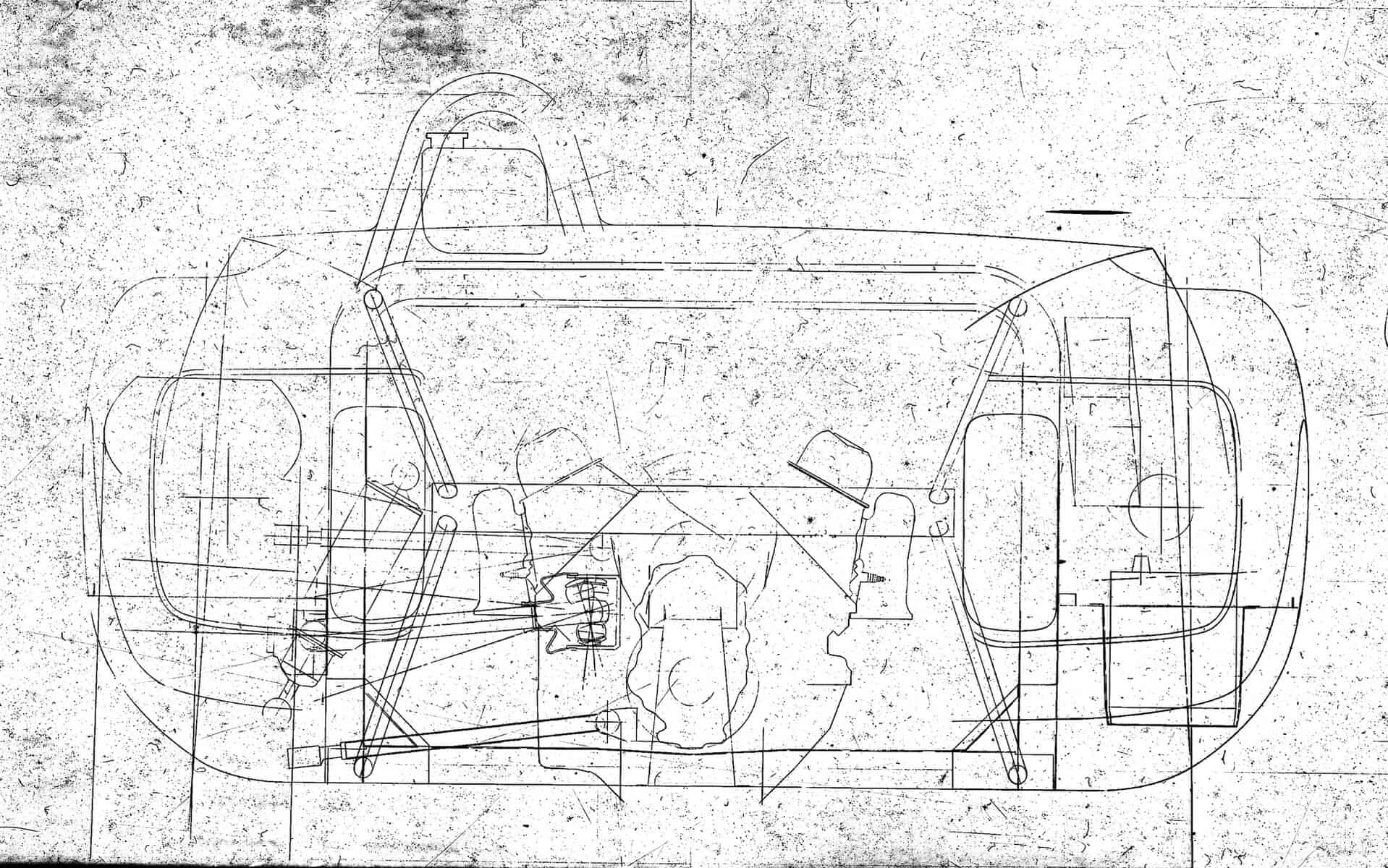
Though a limited-slip differential was made for the rear-wheel drive, it was never used. Conventional open differentials were kept at both front and rear. Open drive shafts to the wheels had Hooke-type universal joints outboard at the rear, with constant-velocity joints at the outer ends in front. Inboard ends of all four shafts had pot-type universal joints that allowed plunging movement of the shafts as the suspension flexed. Unlike many 4WD cars, no attempt was made to mount the brakes inboard. Girling wheel cylinders were adapted to wider caliper bridges to accommodate ventilated brake discs at the wheel hubs.
The suspension design for CERV II was disarming in its simplicity. “The front roll center height is about 3.5 inches,” said Duntov, speaking of its parallel-wishbone layout. “That’s a standard number with me. At the rear it’s about 3 inches above the ground.” Trailing radius rods locating the rear hub carriers and reversed wishbones were angled to give a mild anti-squat effect.
On a four-wheel-drive car there’s a tendency for the front to lift under the direct influence of drive forces. To counteract this Walt Zetye built an anti-lift effect into the front suspension by inclining the axis of the lower wishbone pivots upward toward the rear at an angle of 8 degrees to the horizontal.
Unusual on a car intended for racing were rubber bushings for the inboard wishbone pivots; Zora felt that they should be used for their simplicity and shock absorption where the design didn’t demand a hard-surfaced bushing. CERV II’s rear hub carriers were machined steel and those at the front cast nodular iron with forged-steel steering arms. Outer ball-joint locations at the front were angled to give a steering axis that intersected with the ground 3 inches inboard of the center of the tire patch.
Concentric coil springs and adjustable Armstrong shock absorbers were fitted at all four wheels. Their placement at the front provided an object lesson in the packing of a lot of machinery into a small space. Ahead of the front suspension was a rack-and-pinion steering gear, built by GM’s Saginaw Division to Duntov’s requirements. It needed only 1.8 steering-wheel turns from lock to lock.
Fabricated steel arches carrying the front-suspension components were welded to the monocoque tub, adopted instead of the tubular space frame used for the 1962 study. Like that of Ford’s GT40, the CERV II’s tub was fabricated from sheet steel, 0.025-inch thick instead of the 0.024- and 0.028-inch thicknesses used by Ford. The tub began at the footwell, extended back around the fuel cells at the sides — where it was stiffened by glued-on aluminum braces — and ended at the transverse firewall behind the seats.
From the firewall to the rear, the big V8 was the major frame member, a design technique that later became common but was then rare and adventurous. The engine was attached to the firewall at the front and to a 2.5-inch transverse tube at the back, above the torque converter, this being braced also by two 1.0-inch tubes at each side of the engine.
Initial tests in torsion showed that the complete frame structure was well below par with a stiffness of 2,000 pound-feet per degree. With the curve of frame deflection in torsion showing a sharp break through the engine area, measurements of the engine’s cylinder bores showed they were being distorted significantly by the application of torsion to the frame. The addition of a four-legged tubular brace above the engine raised stiffness to the more satisfactory level of 5,000 pound-feet per degree. This was however less than half the 12,500 lb-ft figure quoted by Ford for its GT40.
At the time CERV II was created, driving positions were sinking lower and lower to reduce the frontal areas of the power-poor 1.5-liter Formula 1 cars. Duntov decided not to cater to this trend because his car was designed to do its job at relatively low speeds, through better acceleration and cornering, and would have a plethora of peak power with which to generate any required maximum speed. Using a more upright seating position allowed Zora to keep his car short, with a 90-inch wheelbase and 157-inch overall length. Front and rear tracks were set at 53.5 inches and overall width at 66 inches.
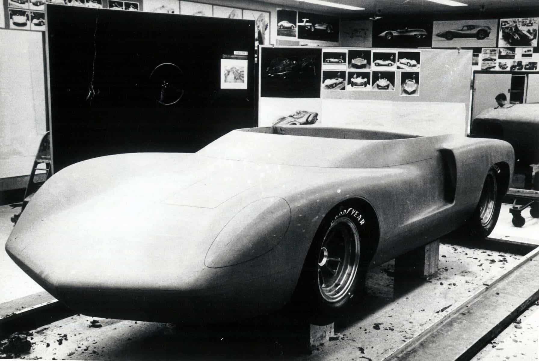
Around CERV II’s upward-ducted front radiator — a Duntov feature dating from the Corvette SS — and built-in roll-over bar Larry Shinoda and Tony Lapine styled a bold body shape in the styling department’s underground studio. For the German-born Lapine this was one of his last major projects before he returned to Europe, to Opel, before becoming director of styling for Porsche.
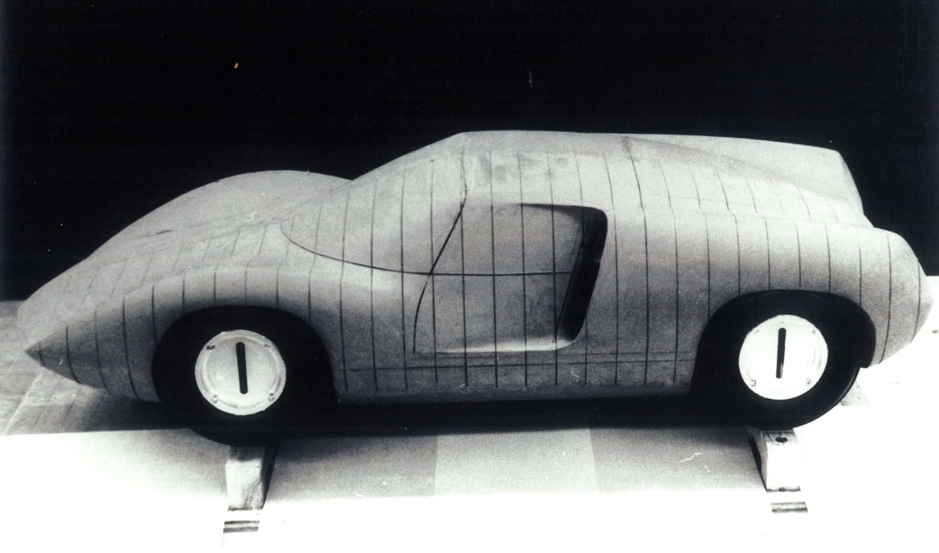
Their roadster shape executed in fiberglass had a low, peaked nose and indentations at the rear with ports for the twin tuned exhaust pipes that were part of the original plan. Quarter-scale models were tested in a California tunnel to refine the shape before the full-size contours were confirmed.
Tests showed that the body worked well. Only a slight curve in the windshield was needed to deflect air completely clear of the driver. After high-speed trials showed instability, a spoiler called a “cow’s tongue” by Duntov was fitted at the rear, protruding from the transverse slot in the engine cover in such a way that it could be deployed when needed. This made CERV II entirely stable at the 214 mph it reached on the Milford five-mile track with a high final-drive ratio and the 377-cubic-inch pushrod engine.
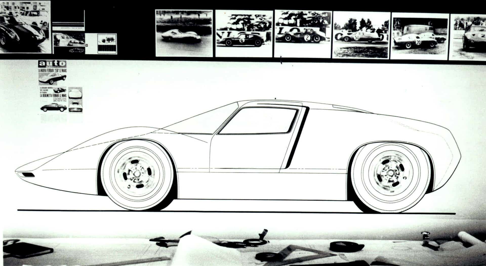
The designers also modeled a coupe version of the CERV II. This had its water radiators mounted in the rear quarters of the body, requiring substantial scoops along the sides. This alternative design allowed the nose to be lower and sharper.
Continued next week….